METHODS OF VIEWING AN OBJECT IN ORTHOGRAPHIC PROJECTION
ORTHOGRAPHIC PROJECTION THREE-VIEW (ORTHOGRAPHIC PROJECTION)
A. Meaning of Orthographic. The term orthographic comes from the Greek word “ORTHOS” and “GRAPHOS” which mean straight line drawing.
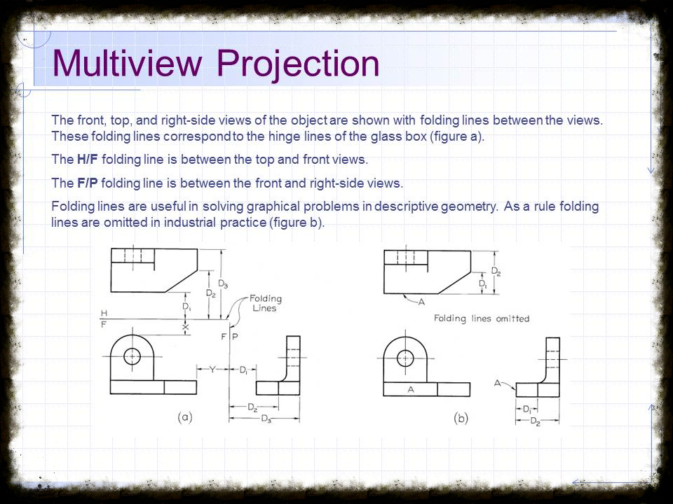
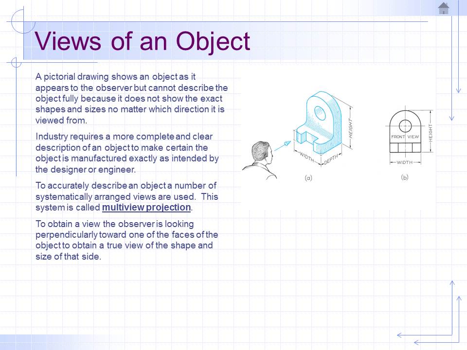
B. Definition of Orthographic Projection. Orthographic projection is the method of representing the exact shape of an object into two or more views on planes generally at the right angles to each other by extending perpendiculars from the object to the plane.
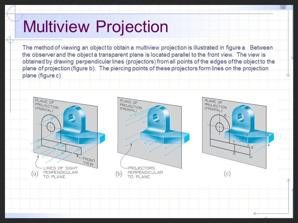
ORTHOGRAPHIC VIEWS VIEW – A TERM IN ORTHOGRAPHIC PROJECTION WHICH IS ILLUSTRATED BY EXTENDING PERPENDICULARS TO THE PLANE FROM ALL POINTS OF THE OBJECT. THE THREE PLANES OF PROJECTION FRONTAL PLANE – THIS SHOWS THE SHAPE OF THE OBJECT WHEN VIEWED FROM THE FRONT. This will show the distance from left to right and from top to bottom.
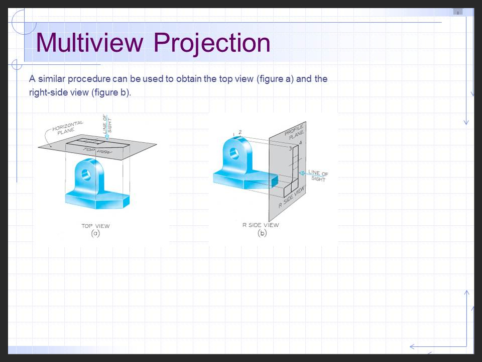
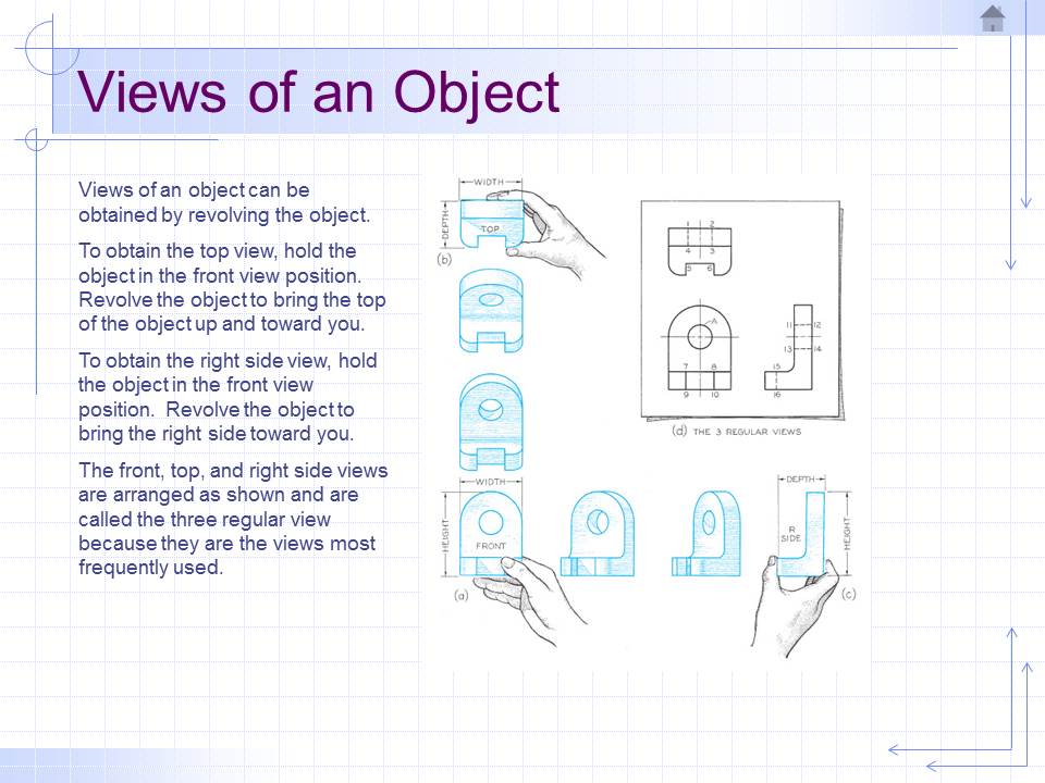
HORIZONTAL TOP PLANE – The projection on this plane is found by extending perpendiculars to the transparent plane from the object, it will give the appearance of the object is if viewed from directly above and shoW the distance from top to rear, and from left to right.
PROFILE OR SIDE PLANE – This will show the shape of an object when viewed from the side and show the distance from the side and show the distance from bottom to top and from left to rear.
Note: In orthographic projection (three views) the picture planes are called planes of projection and the perpendiculars are projecting lines or projectors.
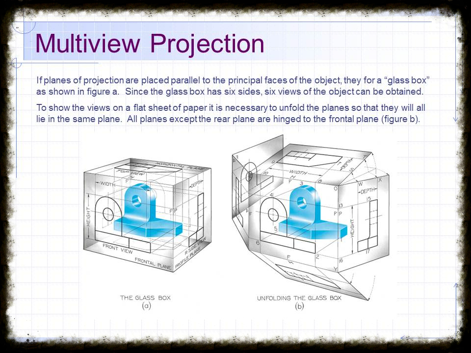
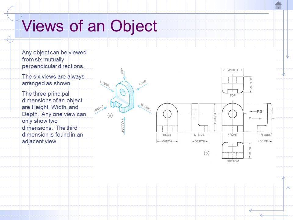
THE SIX PRINCIPAL VIEWS FRONT VIEW, VERTICAL PROJECTION, OR FRONT ELEVATION – the projection on the front plane.
SIDE VIEW, PROFILE PROJECTION, SIDE ELEVATION, OR SOMETIMES CALLED END VIEW OR END ELEVATION – the projection on the side or profile plane. This is further identified as the right side view or left side view if viewed from the right or left respectively.
TOP VIEW, HORIZONTAL PROJECTION, OR PLAN – the projection on the horizontal plane. BOTTOM VIEW – a bottom view will be obtained by reversing the direction of the sight from the top. Rear view – this view will be obtained by reversing the sight of the front view.
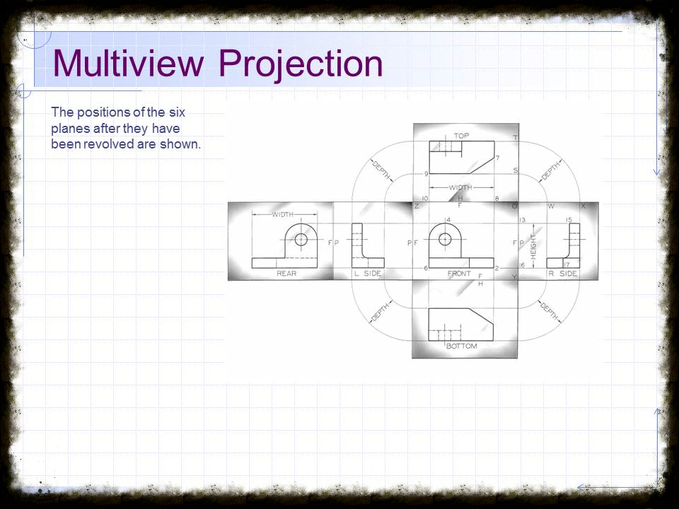
Principles of Projection The top view is directly over the front view.
The side views are in line horizontally with front view.
The depth or width of the side view is exactly the same as the width or depth of the top view.
A surface parallel to a plane of projection is shown in its true size and shape. The surface perpendicular to the plane of projection is projected on that plane as a line.
A surface inclined to a plane of projection is shown as a foreshortened surface.
A line parallel to a plane of projection is shown in its true length.
A line perpendicular to a plane of projection is projected on that plane as a point.
A line inclined to a plane of projection is projected shorter than its true length. No line can be projected longer than itself. No surface can be projected greater than its area.
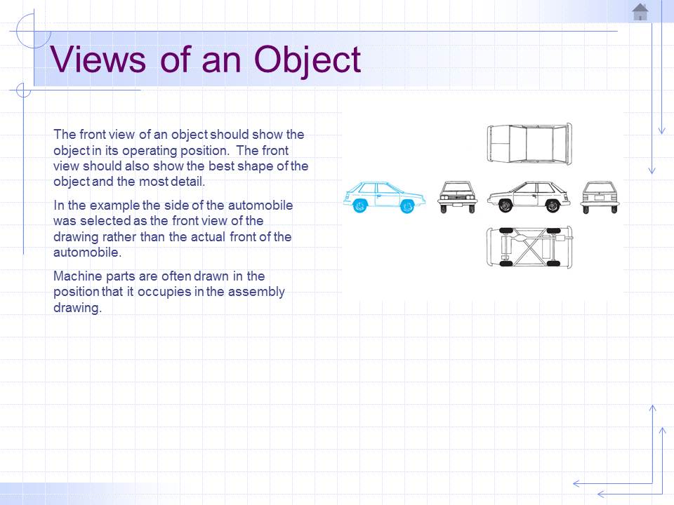
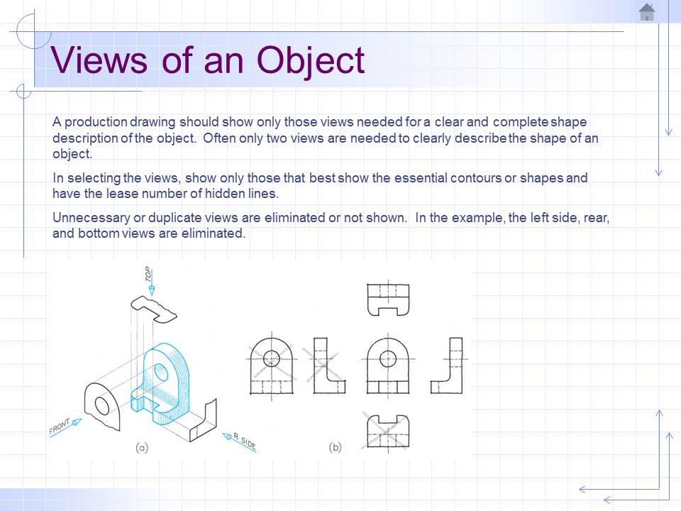
Selection of Views In practical work, it is very important to choose the combination of views that will best describe the shape of the object, Often, only two views are necessary as in cylindrical shape, which, if on a vertical axis, requires only the front and top views, and if on a horizontal axis, only a front view and side view.
CONICAL AND PYRAMIDAL SHAPES may also be described in two views. On the other hand, some shapes will need more than three regular views for adequate description of the object.
SYSTEMS OF ORTHOGRAPHIC PROJECTION
FIRST-ANGLE PROJECTION – An object is projected to the planes and planes are open up on one plane, the top view would evidently fall below the front view, and if the profile plane is added, the view of the left side of the figure would be to the right of the front view.
THIRD-ANGLE PROJECTION – This is the official American Standard universally adopted in the U.S.A. and Canada. If the horizontal and vertical planes of projection should be extended beyond their intersection, four dihedral angles would be formed, which are called, in order, “first”, “second”, ”third”, and “fourth” angles. The object might be placed in any of the planes and the planes folded about their intersection, Description and Definition of Technical Term Isometric drawing is one kind of pictorial drawing.
ISO means EQUAL and METRIC means MEASURE: hence equal measure
Characteristics: In isometric drawing, three faces or surfaces of an object are shown, the top two sides.
THREE AXES OF ISOMETRIC DRAWING:
(1) Vertical axis
(2) left 30 degrees cross-axis
(3) Right 30 degrees cross-axis
To make an isometric drawing: Draw the vertical axis and along it lay the height. Draw the left and right 30 degrees cross axis. On these axes, measure the length and the width of the object. Draw vertical edges. Draw lines parallel to the measured length and width to complete the three faces of the object. Trace the visible edges.
Note: In drawing isometric views its preferred to start from the bottom of the vertical axis rather than from the top. Non-isometric lines – edges whose projection on drawings are not parallel to one of the isometric axes.
1. METHODS USED WHEN THE OBJECT CONTAINS MANY NON-ISOMETRIC LINES:
BOXING METHOD (CRATE METHOD) Offset method In the first method, the object is enclosed in a rectangular box, which is drawn around it in orthographic projection. The box is illustrated in isometric drawing and the object is located in it by its point of contact.
In the second method, the object is made up of planes on a number of different angle.
Isometric circles and arcs occur so frequently that they are usually drawn by four-centered-approximation method which is sufficiently accurate for all ordinary work.
OBLIQUE DRAWING when the projectors make an angle other than 90 degrees with the picture plane the resulting projection is called “oblique projection”. Oblique drawing is similar to isometric drawing by having three axes representing angles to each other, being on a plane parallel to the picture plane.
The third or cross axis may be at an angle to the horizontal plane; but 30 degrees and 45 degrees are generally used. It is thus more flexible than isometric drawing. Any face parallel to the plane of projection will show without any distortions, an advantage over isometric drawing, and be of particular value in the representation of the objects with circular or irregular outline.
RULES IN OBLIQUE DRAWING:
Place the object with the irregular outline or contour parallel to picture plane. Preferably, the longest dimension should be parallel to the picture plane. In case there is a conflict between the two rules, the first should always have precedence, as the advantage of having the irregular face without distortion is greater than that gained by second rule.
Other Forms of Pictorial Drawing: Dimetric Projection Trimetric Projection Cabinet Drawing Perspective Drawing: Perspective drawing is the representation of an object as it actually appears to an observer located at a particular station point. Geometrically, it is the figure resulting when the cone rays from the eye to the object are intersected by vertical picture plane.
There is a distinction between “ARTISTS PERSPECTIVE” and “GEOMETRICAL PERSPECTIVE”.
In the “ARTISTS PERSPECTIVE”, THE ARTIST DRAWS THE OBJECT AS HE SEES IT PROJECTED ON THE SPHERICAL SURFACE OF THE RETINA OF HIS EYE,
while the GEOMETRICAL, OR MECHANICAL PERSPECTIVE, THE OBJECT IS PROJECTED ON A PLANE AS IN PHOTOGRAPH, EXCEPT IN WIDE ANGLES OF VISION WHERE THE DIFFERENCE IS NOT NOTICEABLE.
TWO KINDS OF PERSPECTIVE:
(1) PARALLEL PERSPECTIVE – ONLY ONE VANISHING POINT (2)ANGULAR PERSPECTIVE – TWO VANISHING POINT
thanks for visiting my site and hope you learn a lot from my orthographic projection illustrations.
For Questions you can email me at hmbm26@gmail.com
METHODS OF VIEWING AN OBJECT IN ORTHOGRAPHIC PROJECTION
© Copyright orthographicprojection-hmbm